Elogrid First Piloting
Author: Juha Tanttari
Estimated reading time: 10 minutes
The Elogrid product (pat. Pend.) is developed and designed in Elomatic’s technical analysis team together with the marine business unit. The purpose of the device is to contribute fuel savings in ships equipped with bow thruster tunnels, and increase thrust from the transverse propellers. The device is set in tunnel openings to prevent water entrance into the tunnels when the ship is steaming forward, and when maneuvering the Elogrid blades set in radial direction, it operates as stators decreasing swirl and increasing jet axial momentum.
Now the first delivery of Elogrids has been realized to Viking Line M/S Gabriella, and the first experiences and feedback from the ship are available. The delivery includes CFD (Computational Fluid Dynamic) calculations, dimensioning, design, production with the subcontractor, supervising of the installation and measurements with data analysis.
Dimensions and design
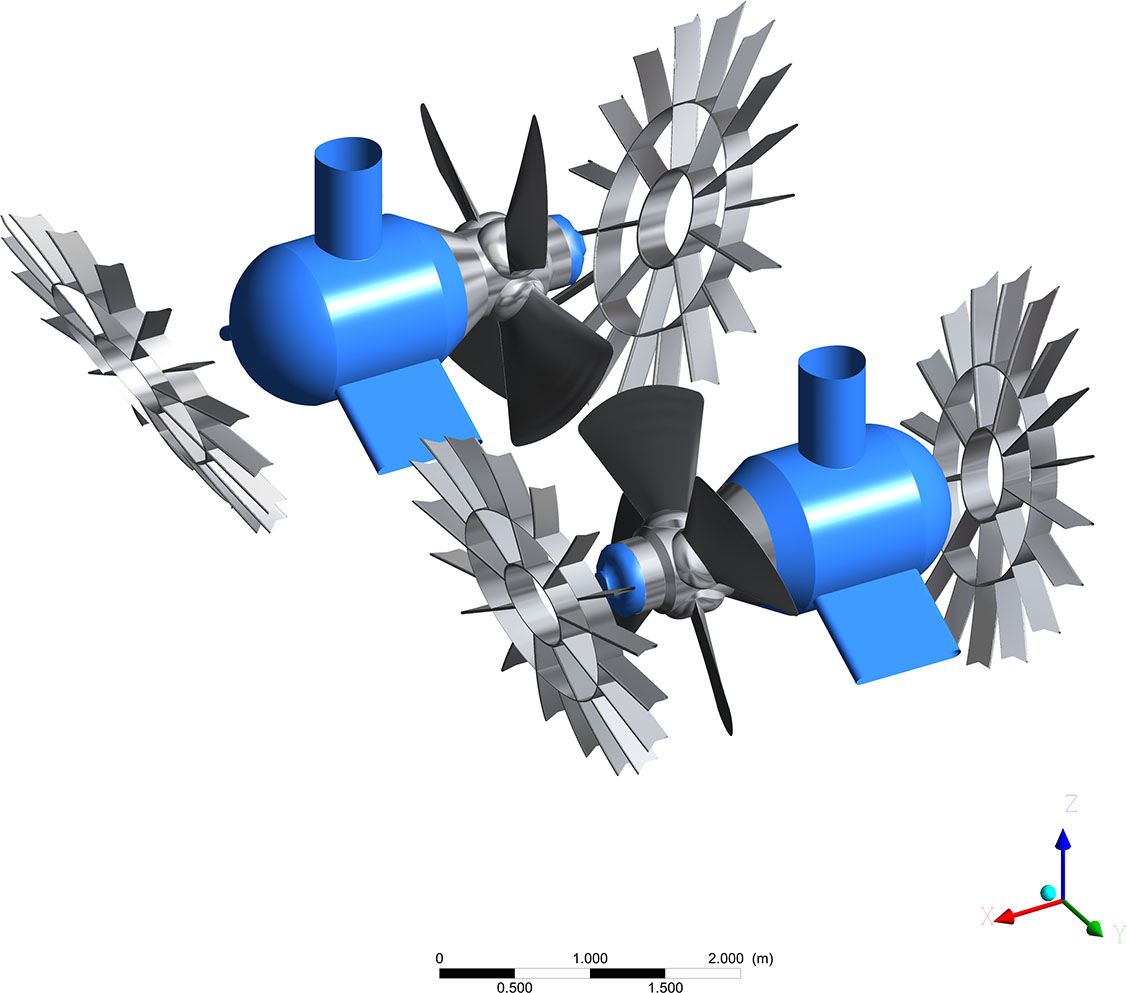
The Elogrid 3D model was produced based on ship drawings and laser scan documents from the client.
CFD models for analyzation of grid impacts were generated for the ship moving at a given speed range and maneuvering at a given thruster propeller rotational speed and pitch angle. The simulations for the Gabriella were conducted for comparison with and without Elogrids.
FEM calculations were conducted in order to detect the grid nominal frequency, stress and deformation in the worst possible load conditions.
The grid shape has been carefully designed based on local flow directions and hull form. The grid is curved in all directions, uniform with hull surface form at the openings. The flow simulation has been done including tunnels with and without grids.
The simulations proposed 2–2.5% fuel savings at the speed range of interest when sailing straight ahead, and thrust improvement was estimated to be between 1.6–3.6% with Elogrids installed. The actual savings are higher in typical conditions where wind or maneuvering is causing drift that leads to a higher flow rate through the tunnels.
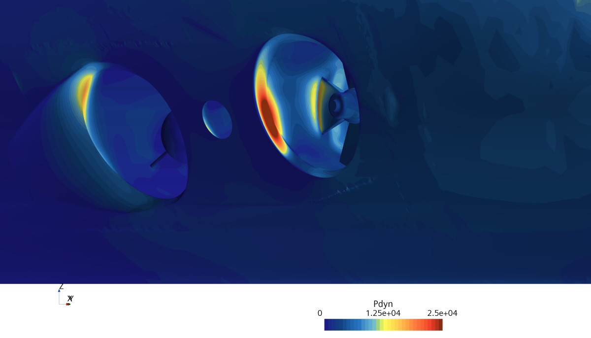
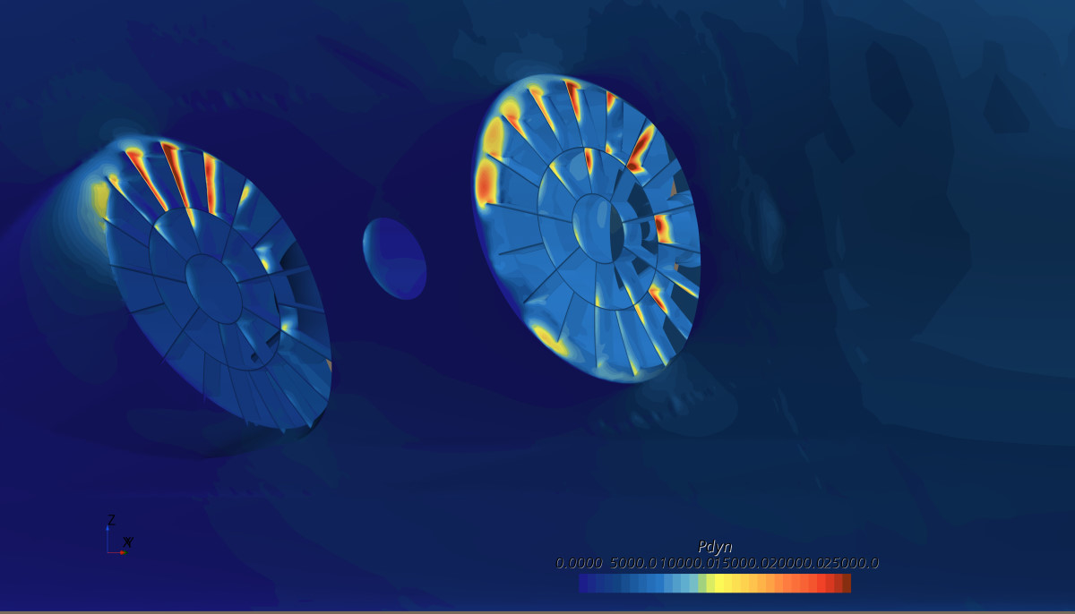
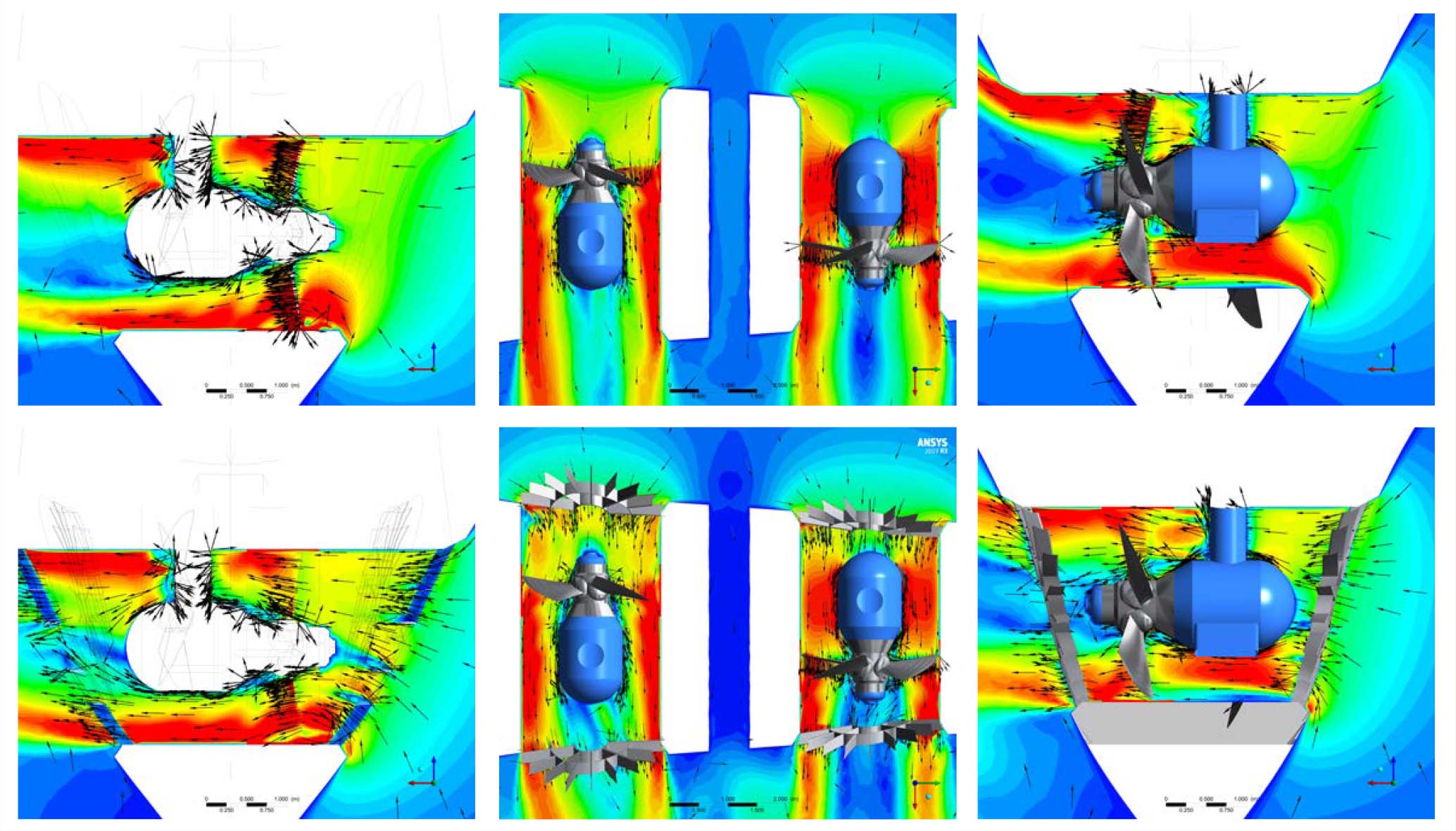
The hydrodynamic pressure shown in Figure 3 indicates the positions which contribute to pressure resistance from the ship movement. The grids prevent water passing through the tunnels and therefore the resistance from tunnels and grids together remain lower.
The velocity contours in Figure 4 show a much higher amount of water circulation and flow through the tunnels without grids when sailing ahead. The propeller at 0° position is slightly blocking the flow allowing a higher flow rate from the pod side.
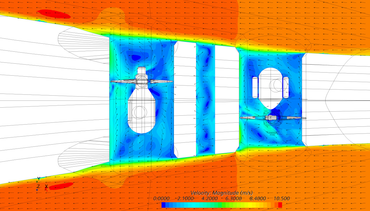
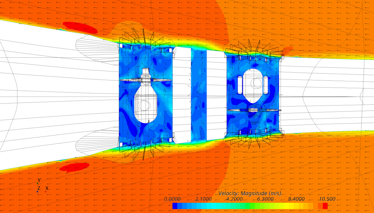
Figure 4: Gabriella water passing through the tunnels.
The thrust is summed from all components on which the propeller induced jet impacts. Highest thrust forces are detected from the propellers, but also the bevels at openings and the hull surface close to bevels contribute thrust on the suction side and possibly losses on the pressure side – depending on how they are designed.
The propeller bossing and strut generate losses that decrease the thrust as well as conventional grids, however the new Elogrid design can contribute thrust forces with stator impact and secondly improve the flow pattern into the propeller suction.
The grid stress and displacements remained on an acceptable level even in the tough ice load conditions shown in the figures. The nominal frequency is much higher than that contributed by fluid force vibrations, which means no risk of resonating should be expected.
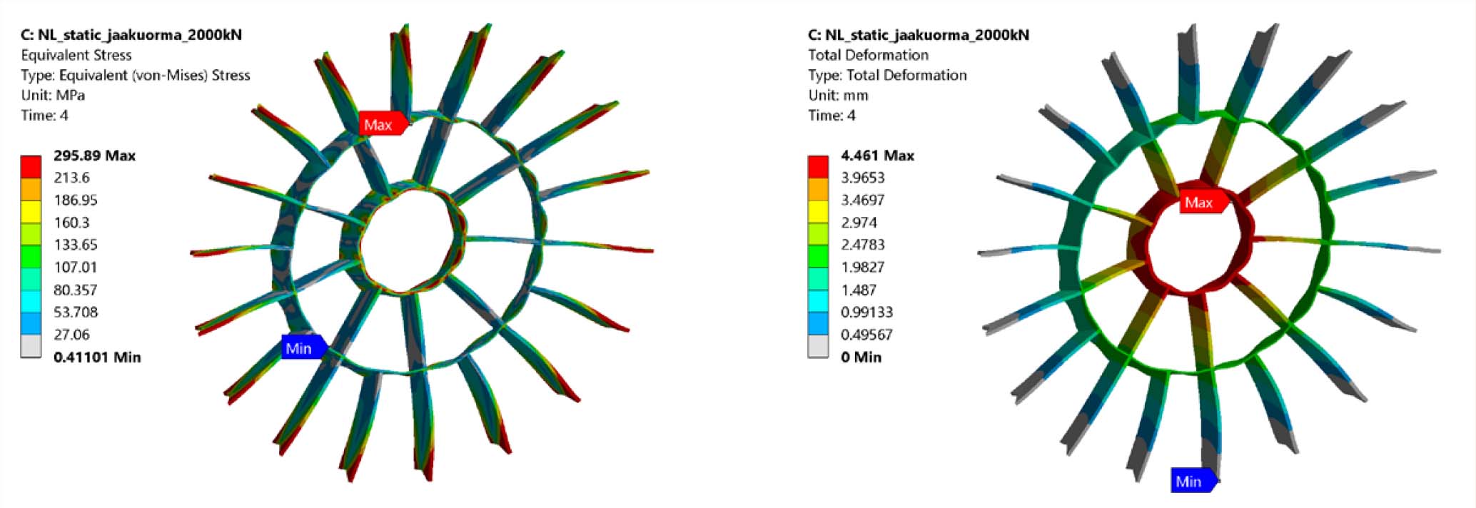
The Elogrid drawings were made according to the 3D model for production and installation, slightly modified from fluid dynamics design, based on the ice load demands detected by structural analysis.
The grid material stainless steel is selected to ensure durability for the product at demanding conditions on tunnel openings.
Production and installation
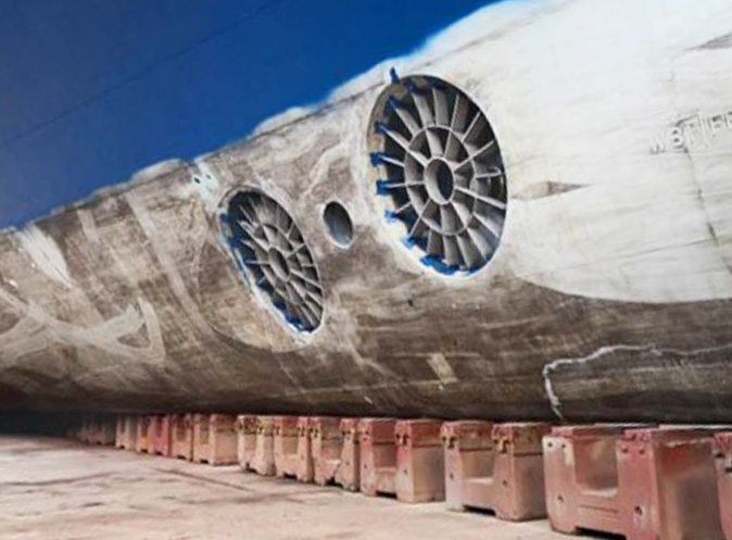
VL Gabriella has two 2.4 m tunnels meaning four Elogrids should be manufactured to cover each of the openings. The devices are manufactured in Turku Finland by Synkronex, which specializes in high quality product manufacturing for marine vessels. The manufacturing procedure demands several weeks due to the complicated structure of the device. Each component to be welded into the Elogrids is different and should be treated in a certain way – tolerances for the assembly are quite tight to ensure the expected performances based on simulations.
The Gabriella drydocking was at Fayard Denmark. One of Elomatic’s specialists was supervising the installation to ensure high quality and also that the complicated structure fit together.
The large scallop at the aftmost tunnel requires special attention – incorrect installation would easily contribute to elevated resistance.
The installation of grids was – thanks to the skillful professionals – successful; the immersion together with the right angle should all be correct to ensure the device fits the opening – and the welding should be made correctly to avoid deformations from high temperature and to ensure durable joints.
Measurements and data analysis
The Elogrids are supposed to reduce tunnels’ additional resistance and at least not decrease the thrust forces from the tunnels. The actual impacts in performances were already analyzed with CFD in the design phase, but in this case we had an opportunity to have measurements onboard in ship scale as well.
The measurements were conducted in co-operation with Viking Line and Meyer Turku Shipyard. The Gabriella side thrust was measured before and after the installation of Elogrids in order to find the contributed impact.
The pull tests included separate and combined use of the thrusters with different pitch angles, which was varied between 50–100%.
The ship was aligned with the open dock to keep it more stable during the operation. Four groups were collecting measurement data at the same time while the tunnels were tested. One group on the quay detected force values from a dynamometer log, vibration data was detected right above the tunnels, noise data was registered in the buffet bar on deck 8 and the bridge group was controlling the procedure. All the ship data was collected in the onboard energy management system, Blueflow.
The main difference during the tests was wind speed, which was logged in Viking Line’s operation data system Blueflow – and compensated for in force calculations.
All the force data from the dynamometer, wind values, propeller pitch and power consumption data from the Blueflow system, vibrations and noise data were collected and average values calculated for comparison of test cases.
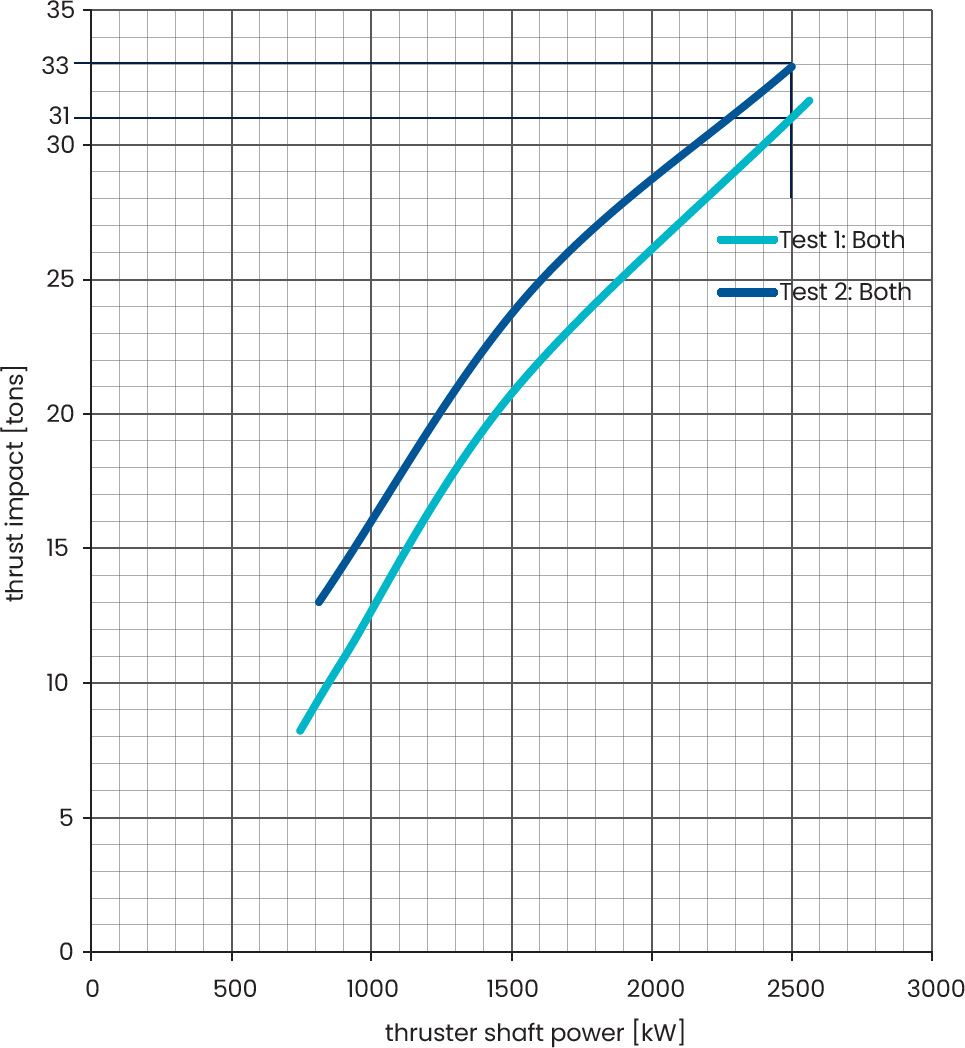
According to the collected data, thrust improvement with grids was 5–10% when values are compared at the same thruster shaft power rate. The difference is larger at lower power rates.
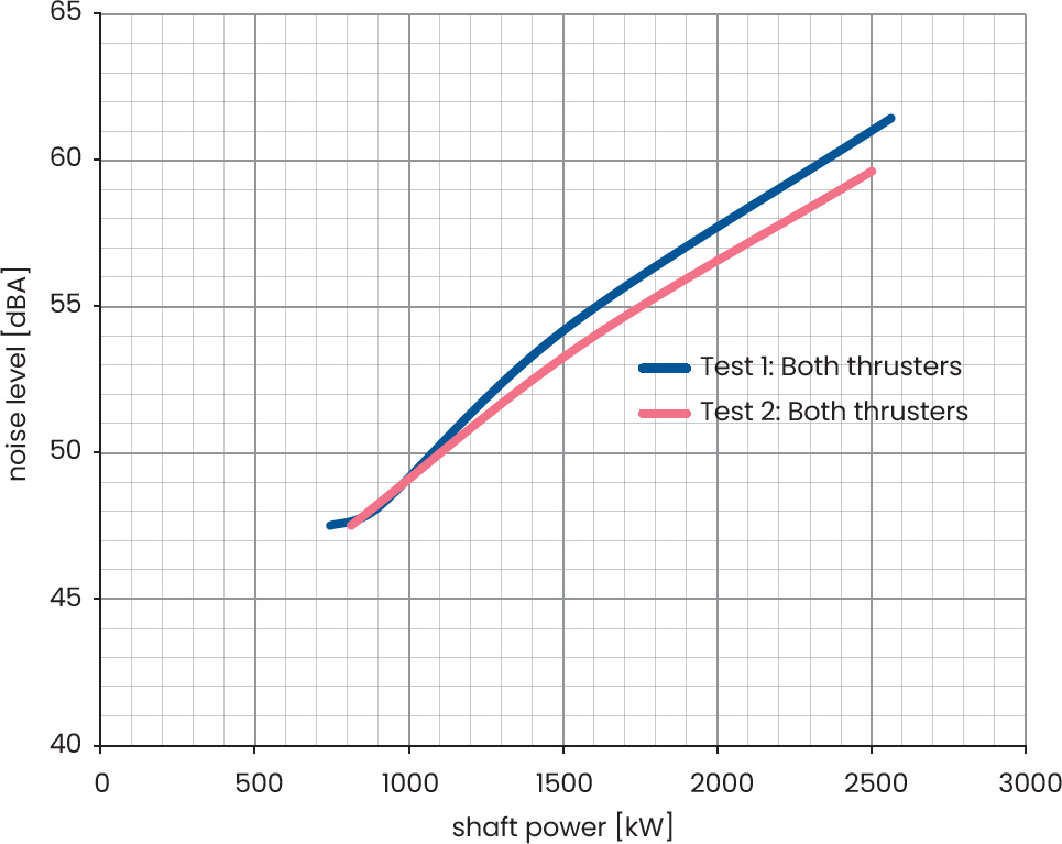
Vibration and noise values were detected, and average values were compared. The vibration values were reduced by 12% on average, and noise level – which is mainly contributed to by vibrations – was reduced by 1.9dBA from 61 to 59dB(A) when both thrusters were in use. Fore tunnel noise was about the same with Elogrids, and the aft tunnel noise level was reduced. The fore tunnel is less noisy in general. The background noise was relatively low, meaning the measured noise was practically all from the thrusters.
Elogrids’ impact on ship tunnel additional resistance is detected comparing Blueflow data from ship propeller pitch and speed versus speed over ground. The values are captured from journeys before and after drydocking of 2018 and 2021 to see the impact of drydocking separately.
Ship draught is detected separately from Napa loading condition sheets – slight differences are detected in draughts. On journeys after installation of Elogrids she has 8cm more draught.
The data was filtered removing high wind speed situations (>7m/s) and ship speed change periods from the filtered data.
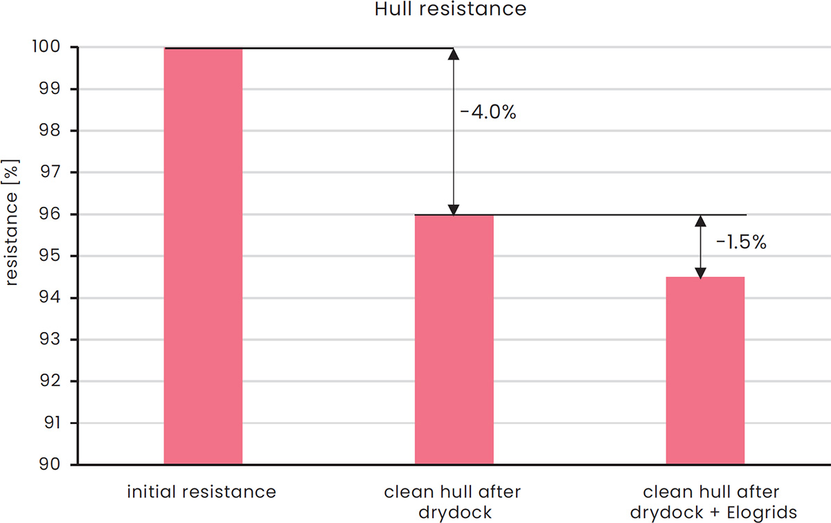
Finally, after smoothing the ship speed over ground vs resistance data, we notice the hull service at dry docking contributed a 4% reduction in resistance, and installing Elogrids contributed an additional 1.5% reduction.
The accuracy of operational data improves when more data is collected – but during the time needed to collect data the hull surface is becoming less clean and that might affect the results. The number of variables during the ship journeys is enormous and therefore comparisons are challenging and time consuming.
Conclusions and feedback
The piloting of Elogrids was successful thanks to the professional group involved in the project, the product was delivered in the tight timeframe agreed, the quality of the product installed was high – and performances detected were as simulated and designed; development is needed in the delivery process in general to keep the expenses of the product as desired to satisfy the average payback times expected by ship owners.
Gabriella has been operating after the installation of Elogrids now for the whole time since May, after a long period in dock due to Covid limitations on ferry traffic. The experiences from these have been good in general, according to Gabriella’s Captain:
“After the installation of Elogrids I really feel the difference in lower vibrations on deck already during the testing. The maneuverability of the vessel is clearly improved compared to original. I would have not expected to notice such a significant effect. The personnel I have met from Elomatic have all been true professionals.”
Captain Tomas Karlgren of Viking Line
The fuel saving potential and other benefits seen in Gabriella has led VL to invest in Elogrids for the next drydocking vessel, and the design for the device has already been started.

Juha Tanttari
M.Sc (Mech. Eng)
Juha Tanttari has 20 years’ experience of working in fluid dynamics consulting. His experience covers a vast range of industrial segments including marine hydrodynamics and aerodynamics, project management and sales. He is currently of Lead Consulting Engineer, in Technical Analysis.
juha.tanttari@elomatic.com
Want to know more? Check out these related articles:
Elogrid™
Elogrid is a cutting-edge solution crafted by our team, dedicated to maximizing energy efficiency and minimizing environmental impact in maritime operations. By seamlessly integrating advanced engineering methods and innovative design principles, Elogrid offers a multifaceted approach to enhancing vessel performance.
Shipowners and Operators
We develop innovative solutions that can minimize the environmental impact and operating costs of your ships.