31/12/2019
Simulation of deflagration in exhaust systems – An application of CFD in safety engineering

Computational Fluid Dynamics (CFD) is being increasingly used in safety engineering to simulate toxic gas dispersion, fires, and explosions. Experimental studies in this area are dangerous, difficult, and expensive. They are also often confined to a relatively small scale compared with practical situations such as fires in chemical plants and explosions in coal mine tunnels.
Empirical approaches can also be found in different safety codes. They are used to assess the risk and the effects and consequences of accidents. CFD numerically solves the governing equations of fluid flows, which can involve heat transfer and chemical reactions, to predict the flow field. It is a powerful tool which, in addition to the valuable experimental studies and the empirical approaches, can provide data for the effects and consequences of specific accident scenarios, enhance the understanding of possible scenarios, and provide insights into mitigation measures.
Ensuring the adequacy of CFD simulation
While the reliability and the accuracy of CFD simulations is still a significant concern, CFD codes have been approved as a tool in the area of safety analysis. There have also been efforts in ensuring the adequacy of CFD simulation in safety engineering.
PHMSA (Pipeline and Hazardous Materials Safety Administration, U.S. Department of Transportation) has approved a software programme for radiant heat flux and four software programmes for atmospheric vapour dispersion for the purpose of determining the extent of LNG exclusion zones. Exclusion zones are established to protect the public from the potential consequences of the unintentional release of LNG (PHMSA, 2017). In 2006, the Idaho National Laboratory prepared “Processes and Procedures for Application of CFD to Nuclear Reactor Safety Analysis” for the U.S. Department of Energy (Johnson, et al., 2006).
In the EU SUSANA project (SUpport to SAfety aNAlysis of Hydrogen and Fuel Cell Technologies) (FCH, 2017), which concluded in 2016, a model evaluation protocol was developed to support the use of CFD analysis in safety engineering in relation to hydrogen and fuel cell technologies. It was emphasised that the following two aspects need to be addressed to apply CFD with a high level of confidence in the accuracy of the simulation results:
- the capability of the CFD models to accurately describe the relevant physical phenomena
- the capability of the CFD users to follow the correct modelling strategy.
Explosion risk in dual-fuel engine exhaust systems
A dual-fuel engine can run on both liquid fuel (e.g., heavy fuel oil) and gaseous fuel (currently mainly natural gas). Since the combustion of gas leads to significantly lower emissions, the application of dual-fuel engines for marine purposes has been driven by more stringent emission regulations. Dual-fuel engines can also reduce the requirement for extra fuel storage on vessels and help improve efficiency, especially for LNG carriers.
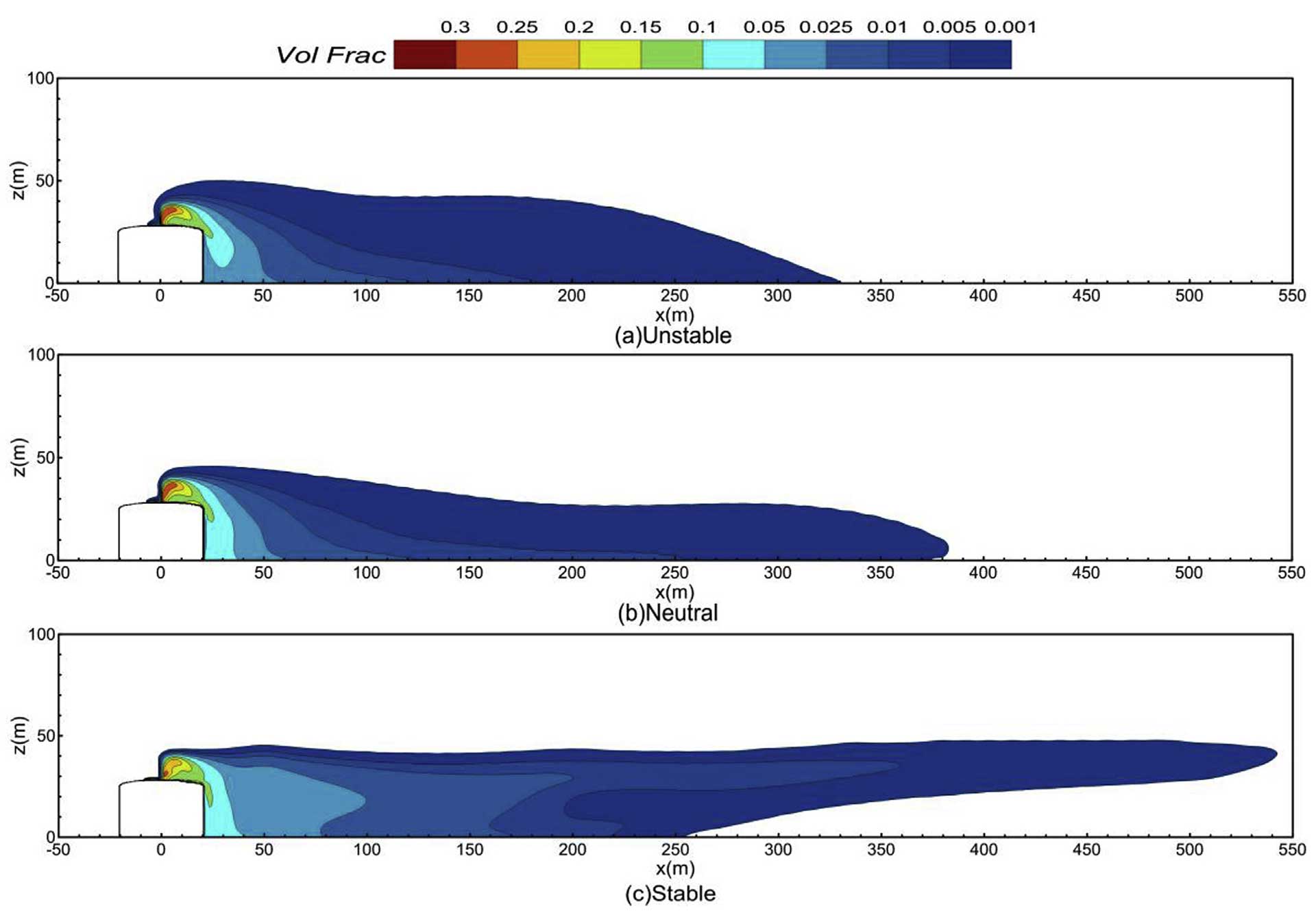
Figure 1. Simulation of the dispersion of LNG vapour released from the top of a storage tank under the effect of different atmospheric stratifications. Unstable, neutral and stable, 180 s from the start. The vertical concentration contours of LNG cloud at the downwind axis. (Guo, Zhao, Wang, Yao, & Hu, 2019).
On marine vessels, the exhaust system of a dual-fuel engine typically consists of an exhaust pipe, a ventilation system, and one or more silencers. It may also include a boiler for waste heat recovery and an SCR reactor for NOx reduction, as well as a bypass line for this equipment.
When an engine runs on gas, there is a risk of unburnt gas entering the exhaust system even though preventive measures are taken. If the gas-air mixture ignites, deflagration will occur and lead to a rapid increase in temperature and pressure inside the exhaust system. This would create an explosion hazard for the equipment and the personnel on board and mitigating measures would have to be taken.
For example, the DNV GL classification rules for ships with gas-fuelled engines require suitably designed and fitted explosion relief systems, unless the exhaust systems are designed to withstand the worst-case overpressure resulting from ignited gas leaks (DNV-GL, 2017). Both one-off rupture discs and reclosable spring-loaded valves can be used.
The arrangement of the pressure relief system, i.e., the number, size, and position of the pressure relief devices, should already be considered in the design of the exhaust system. CFD simulation is a cost-efficient way of evaluating the arrangement of pressure relief devices and to ensure class approval.
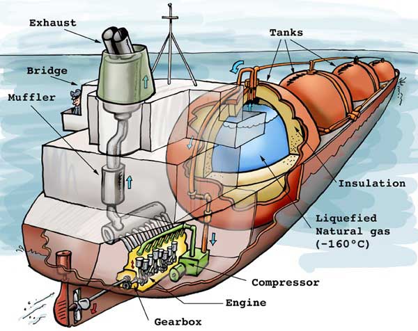
Figure 2. Cutaway illustration of an LNG carrier (Welleman, 2004). Boil off gas from the LNG tanks is used in the engine for propulsion.
Simulation of deflagration in exhaust systems
In order to evaluate the arrangement of pressure relief devices, simulations of deflagration in exhaust systems must be carried out in reasonable gas leak scenarios. In a conservative approach, the worst-case scenario could be included, in which none of the engine cylinders is firing but gas is still being supplied to the engine. In such a case, the gas-air mixture would enter and fill a large part of or the whole exhaust system.
The worst-case scenario is somewhat theoretical, and the probability of it occurring is low. However, if the simulation shows that the pressure relief arrangement can help prevent excess pressure in the worst-case scenario, the arrangement should be sufficient in normal conditions. Less severe but more plausible scenarios could also be included.
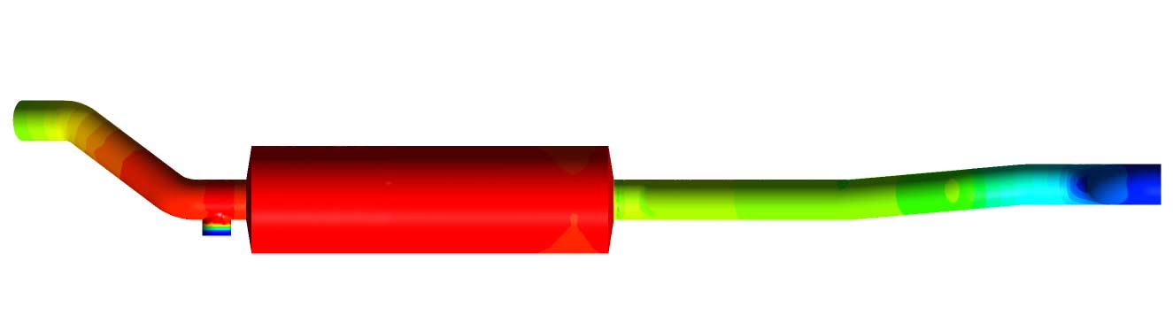
Figure 3. Pressure development during a deflagration simulation.
Adequate details of the equipment, e.g., silencer, should be included in the simulation model to represent the equipment characteristics. In the simulation, a rupture disc should open and release pressure when its burst threshold has been reached, while the size of the opening of a spring-loaded valve depends on the loaded pressure and its design properties.
Transient 3D simulation should be performed so that the propagation of the reaction zones of the gas-air mixture and the pressure waves can be investigated. During the simulation, the pressure history in any part of the exhaust system can be recorded, and the maximum pressures obtained. The maximum pressure can be compared with the pressure limit of the equipment.
A simulation of deflagration in exhaust systems should provide a validation of the arrangement of the pressure relief devices or produce results that can be used to improve the arrangement, e.g., to suggest new positions for the pressure relief devices.
This article was first published in Elomatic’s Top Engineer magazine 2/2019
Want know more?
Computational fluid dynamics services for the process and energy industry
Computational fluid dynamics services for the process and energy industry. The use of computational fluid dynamics (CFD) helps to, for instance, optimize processes, improve performance, reduce energy consumption and ensure safety, without forgetting the environmental aspects.
Fluid Dynamics
With our Computational Fluid Dynamics (CFD) services, you can analyze the fluid dynamics and heat or mass transfer of fluids and thereby develop your products. You also save time and money.